
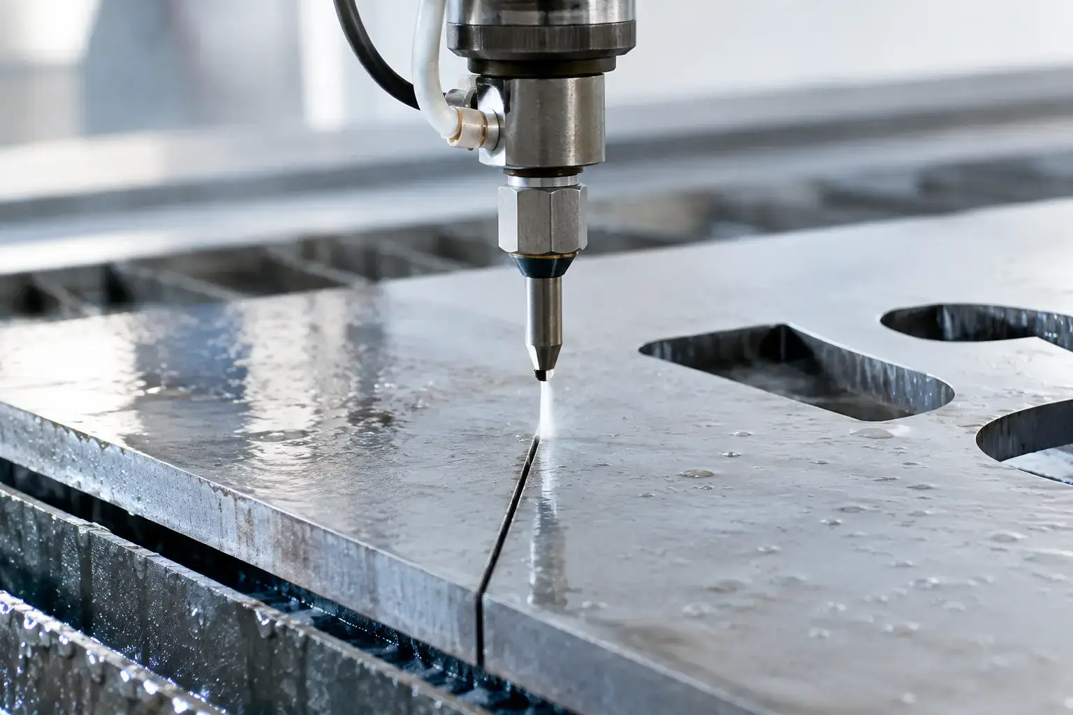
A drawing can be dimensionally correct and still produce an undersized part if the cutting path is not allowed for the material removed by the jet. That removed strip is called kerf. So, what is waterjet kerf width? It is the width of material taken away as the high-pressure water and abrasive stream travels through a workpiece.
For fabricators, builders, engineers and designers, kerf width is not a minor programming detail. It directly affects finished dimensions, hole sizes, slot clearances, fit-up, material yield and the appearance of detailed work. Understanding it helps ensure the part supplied matches the drawing, whether it is a one-off architectural feature, a gasket set or production components for a larger fabrication job.
What Is Waterjet Kerf Width in Practical Terms?
Waterjet kerf width is the width of the cut made by the waterjet stream. It is sometimes described as the path or gap left behind once the jet has passed through the material. On a waterjet cutting job, this is commonly around 0.8 mm to 1.2 mm, although the actual result depends on the material, thickness, cutting settings and required edge quality.
Abrasive waterjet cutting combines water pressurised up to 60,000 PSI with abrasive grit. The stream exits through a small orifice and mixing tube at very high speed, eroding material rather than melting it. Because the cut is cold, there is no heat-affected zone, distortion or hardened edge caused by the cutting process. That makes waterjet highly suitable for stainless steel, aluminium, steel, rubber, stone, tile, composites and many other materials.
The jet itself is not a perfectly fixed-width tool. Its effective cutting width changes with operating conditions. This is why experienced CNC programming and machine setup matter as much as the original CAD file.
Why Kerf Width Changes the Finished Part
If a waterjet followed the exact centreline of an outside profile, the finished component would be smaller than the drawing by approximately the kerf width. If it followed the centreline of an internal hole, the hole would be larger. CNC software prevents this by applying kerf compensation, also known as tool offset.
For an outside profile, the machine offsets the cutting path outward from the finished edge. For an internal profile such as a hole or slot, it offsets inward. The result is that the edge of the cut, rather than the centre of the jet, lands on the intended finished dimension.
This distinction becomes particularly important where parts must fit together. A tab-and-slot assembly, a mounting plate with clearance holes, or interlocking decorative panels can all be affected by a fraction of a millimetre. A kerf allowance that is wrong by only a small amount may create a loose fit, a part that will not assemble, or a visible mismatch in a finished architectural installation.
Kerf also has a commercial effect. It occupies material during nesting, which is the process of arranging parts on a sheet to reduce waste. When multiple components are nested closely, the programmer needs enough clearance between cut paths to retain edge quality and avoid damaging narrow webs of material. Good nesting balances material efficiency with reliable production.
What Affects Waterjet Kerf Width?
There is no single kerf value that applies to every job. Material thickness is one of the main factors. As material gets thicker, the jet can spread slightly as it travels through the plate, especially where faster cutting speeds are used. This can create a wider cut at the bottom than at the top, known as taper.
Cutting speed also makes a noticeable difference. A slower cut generally gives the jet more time to cut cleanly through the material and can improve edge finish, while a faster cut supports shorter lead times but may produce more striations or a less refined lower edge. The best setting depends on the application. A concealed bracket may not need the same finish as a visible stainless steel panel or precision mechanical component.
Other influences include water pressure, abrasive flow rate, nozzle condition, the diameter of the orifice and mixing tube, material hardness and the cutting head height above the workpiece. A worn mixing tube, for example, can widen the stream and reduce consistency. Regular machine maintenance and verified settings are essential for repeatable results.
Material Behaviour Matters
Different materials respond differently to the same waterjet setup. Rubber and foam are generally cut without abrasive and can have different kerf characteristics from 20 mm stainless steel. Ceramic tiles, stone and glass may require careful handling to manage edge quality and reduce the risk of chipping. Aluminium can be cut accurately with waterjet, but the required finish and thickness still determine the best speed and settings.
For this reason, an accurate quotation and cutting plan should consider more than material type and overall dimensions. Thickness, tolerance, quantity, critical features and the part’s final use all influence the chosen process.
Kerf Width, Tolerances and Small Features
Kerf width is particularly relevant to tight tolerances and small internal details. A waterjet can produce highly accurate profiles, but designers need to allow for the physical limits of the cutting stream. A very narrow slot may be impractical if it is close to, or smaller than, the effective kerf. Likewise, sharp inside corners will naturally have a small radius because the stream has width.
Where a drawing calls for a fine internal radius, a narrow web or a closely spaced pattern, it is worth discussing the intended outcome before cutting begins. In some cases, waterjet is the best option because it avoids heat distortion and handles thicker or heat-sensitive materials exceptionally well. In other cases, high-definition laser cutting may be more suitable for thin metal features where speed and a narrower cut are the priority.
The right process is not simply about which machine can make the shape. It is about the material, thickness, edge requirement, feature size, quantity and how the finished part needs to perform.
Taper and Edge Quality
Taper is often confused with kerf width, but they are not the same thing. Kerf is the width of the material removed. Taper is the difference between the cut at the top surface and the cut at the bottom surface.
Modern waterjet machines can manage taper through suitable programming, cutting speeds and dynamic cutting head technology where available. However, there is always a practical trade-off between speed, surface finish and the degree of precision required. A job requiring close-fitting machined-style components deserves different settings from a general fabrication plate where the cut edge will be welded, dressed or hidden.
Clear communication about the critical dimensions helps the cutting team apply the correct quality level from the outset. Supplying a clean DXF or DWG file, identifying any press fits or clearance-critical holes, and noting visible faces can prevent expensive rework later.
How Kerf Compensation Is Applied
In most professional waterjet work, the customer does not need to manually add kerf to every dimension in their drawing. The supplied drawing should normally represent the required finished part size. The CNC programmer then applies the correct offset based on the selected cutting parameters.
Problems can occur when kerf has already been added to a file without being identified, or when a design has been prepared for another cutting method and then used for waterjet without review. A laser, router, plasma cutter and waterjet do not necessarily produce the same kerf or respond to material in the same way.
For repeat production work, it can be useful to approve a first-off part before the full batch is cut. This is especially sensible for complex assemblies, custom screens, non-standard material, high-value plate or components with very tight fit requirements. A first-off check confirms that the actual fit matches the design intent before more material is committed.
Design Tips for Better Waterjet Results
Start with finished dimensions, not assumed tool paths. If you need a 10 mm hole, specify a 10 mm finished hole and allow the cutting provider to determine the appropriate kerf compensation. Where tolerances are critical, state them clearly rather than assuming a general tolerance will suit every feature.
Avoid designing slots that are narrower than the practical kerf for the material and thickness. Consider the effect of inside corner radii where parts need to mate. If a square internal corner is essential for an assembly, a small relief feature may be required. This gives the matching tab or component somewhere to clear the natural corner radius.
For nested or decorative work, leave sensible spacing between fine elements. Thin bridges can move under cutting forces or become fragile during handling, particularly in heavier plate. A small adjustment to a pattern may substantially improve strength, yield and production reliability without changing the visual result.
At Waterjet & Laser SA, the cutting method can be selected around the job rather than forcing every project through one process. That means customers can weigh waterjet’s cold-cut versatility against laser cutting’s speed on suitable thin metals, with the finished requirement guiding the decision.
When to Ask About Kerf Before Cutting
Ask early when parts must interlock, holes locate bolts or pins, material is expensive, or the design includes intricate internal details. It is also worth raising on thick plate, tiles, stone, composite materials and components that need a clean visible edge.
A quick discussion before production can establish whether waterjet kerf width, taper control, lead-in position or cutting quality will affect the result. The goal is not to overcomplicate a straightforward profile. It is to make sure the cutting process supports the way the part will be assembled, installed and used.
The best waterjet job starts with a clear finished-part requirement. When kerf is accounted for properly, the result is accurate components, cleaner fit-up and far fewer surprises on the workshop floor.