
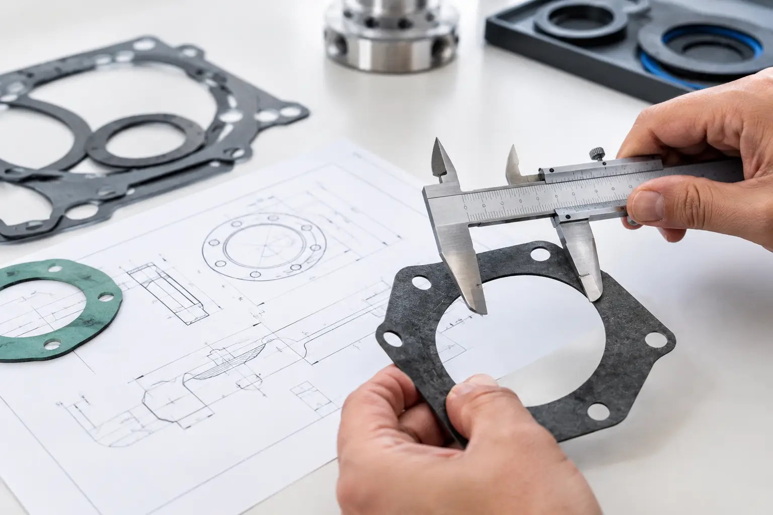
A gasket can look like a simple ring, yet a 1 mm discrepancy at the bore, bolt pattern or sealing land can stop a flange from sealing properly. When a part is being cut for an urgent shutdown, a pump rebuild or a production run, the drawing needs to remove guesswork before material reaches the cutting bed. Knowing how to specify gasket dimensions clearly helps deliver parts that fit first time and perform as intended.
Start with the real sealing requirement
Before measuring an old gasket or drawing a profile, identify what the gasket must seal. The flange arrangement, operating pressure, temperature, medium and bolt load all influence the suitable profile and material. A gasket for a low-pressure water connection may need very different allowances from one used around oils, chemicals, compressed air or abrasive slurry.
The sealing face is the starting point, not the worn or distorted gasket removed from service. Old gaskets can compress, stretch, tear during removal or swell after exposure to fluid. They are useful as a reference, but should not be the only source of dimensions where accuracy matters.
If the mating parts are available, measure the flange faces directly. Confirm whether the gasket sits inside the bolt circle, outside it, within a recess, or over a raised face. Also check that the gasket’s inside edge will not project into the flow path. Material protruding into a pipe or pump bore can create turbulence, wear and contamination issues.
How to specify gasket dimensions from the sealing face
For a standard circular gasket, provide the inside diameter, outside diameter and finished thickness. These dimensions should be stated in millimetres and labelled clearly as ID, OD and thickness. Do not rely on a note such as “suit 100 NB flange” alone. Nominal pipe and flange sizes are useful references, but standards vary and they do not always describe the exact sealing arrangement in front of you.
The ID should suit the open bore or the required clearance around it. The OD should sit fully on the available sealing land without extending beyond the flange edge or interfering with bolts. Where a gasket must locate in a groove or recess, specify the groove dimensions as well as the gasket dimensions, and state any desired clearance.
Thickness requires more consideration than it first appears. A thicker gasket can accommodate some irregularity in mating faces, but it may require more bolt load and can be more prone to extrusion in demanding applications. A thinner gasket may offer better stability, provided the flange faces are suitably flat and the material is appropriate. Specify the actual finished thickness required, rather than describing it only as “thin” or “heavy-duty”.
For non-round profiles, dimension the overall length and width, then identify every internal opening, corner radius, slot and tab that affects fit-up. Give dimensions from consistent datums, such as the horizontal and vertical centre lines, rather than chain-dimensioning features from one another. This approach prevents small measurement differences accumulating across the part.
Define bolt holes and alignment features
Bolt holes are among the most common causes of unusable gaskets. State the quantity of holes, their diameter and their position. For equally spaced holes, provide the pitch circle diameter, number of holes and angular orientation. The orientation matters whenever there is a non-symmetrical feature, such as an offset port, a single locating hole or an irregular outer profile.
For example, a complete instruction may read: “Eight 14 mm holes equally spaced on a 180 mm PCD, with one hole centred on the vertical centre line.” That tells the cutter where the pattern starts as well as how it is distributed.
Slotted holes need their width, overall length, end radius and orientation. If a slot is intended to accommodate installation variation, make that clear. A slot deliberately added for tolerance is different from a slot that forms part of the seal boundary.
Where a gasket includes multiple ports, label each one on the drawing. Similar-looking openings can have different purposes, and a rotated part may not become apparent until installation. A clear “TOP”, “FLOW END” or orientation mark can prevent expensive delays on site.
Set tolerances that suit the job
Every cut part has manufacturing variation, and every application has a practical limit for that variation. Specifying unnecessarily tight tolerances can increase cost and lead time without improving the seal. Leaving tolerances undefined can create avoidable ambiguity.
The right tolerance depends on gasket size, material, thickness, flange design and the consequences of misalignment. A large rubber flange gasket may function well with a more practical tolerance than a small multi-port gasket for precision equipment. Critical dimensions are usually the ID, bolt-hole locations, narrow sealing lands, internal ports and any locating features.
State general tolerances where appropriate, then call out tighter requirements only on critical features. If you are matching a supplied component, include its measured dimensions or provide the component for checking. For repeat production, an approved sample can be valuable because it establishes a physical benchmark alongside the drawing.
Keep in mind that flexible materials behave differently from steel. Rubber and foam can move slightly during handling, while fibre sheet materials may have grain direction or edge characteristics that affect performance. Dimensions are normally specified in the free, uncompressed state unless the drawing says otherwise.
Specify the material, not just the shape
Two gaskets with identical dimensions can perform very differently. The cutting specification should identify the material grade or type, thickness and, where relevant, hardness. If the exact product is known, provide the manufacturer’s material designation. If it is not known, provide the service conditions so an appropriate option can be discussed.
Useful information includes the fluid or gas being sealed, maximum operating temperature, pressure, exposure to weather or UV, and whether food-grade, chemical-resistant or electrical-insulation properties are required. For rubber materials, Shore hardness can be relevant. For compressed fibre, graphite or other specialised sheets, the intended application matters just as much as the profile.
Material selection and dimensioning are connected. A soft, compressible material may need different bolt-hole clearance from a stiffer sheet. A gasket exposed to chemicals may change size in service, so the material’s compatibility should be confirmed before finalising the profile.
Supply a drawing that can be cut accurately
A dimensioned PDF is often enough for a straightforward gasket, provided it includes all critical measurements, material details, quantity and revision number. For intricate parts, a DXF or DWG file is preferable because it gives the cutter a direct profile to review. A scale drawing without dimensions is not a reliable manufacturing instruction, as print settings and imported geometry can change size.
Check the CAD file before sending it. Confirm it is drawn at 1:1 scale in millimetres, contains only the required cut lines, and does not include duplicate lines or hidden geometry. Closed profiles are particularly important. An unclosed line can cause an incomplete cut or introduce uncertainty about the intended edge.
If you are working from a hand sketch, make it legible and include a photograph of the mating flange with a tape measure where useful. A sketch does not need to be elaborate. It does need to establish the shape, dimensions, hole pattern, material and orientation without conflicting notes.
Choose the cutting process around the material
Waterjet cutting is particularly well suited to rubber, foam, fibre gasket sheet and other materials that should not be exposed to heat. The cold-cut process avoids heat distortion and can produce detailed profiles, small holes and intricate internal features. It is also useful where material integrity at the cut edge is a priority.
Laser cutting can be an efficient option for suitable materials and applications, particularly where speed and clean profile cutting are required. The best process depends on the gasket material, thickness, edge requirement, part complexity and quantity. For gaskets, the material should guide the process choice rather than simply selecting the fastest available machine.
At Waterjet & Laser SA, supplying the drawing and the application details together allows the cutting method, nesting and tolerances to be checked before production. That reduces the risk of a technically accurate profile being cut from a material that is unsuitable for the job.
Checking gasket dimensions before cutting
A final pre-cut review is worthwhile, especially for low-volume custom parts. Compare the drawing against the flange or mating component one more time. Verify ID, OD, thickness, bolt-hole count, PCD, orientation, material and quantity. Check that revision numbers match across the purchase order, drawing and CAD file.
For a first-off part with a complex pattern, a simple paper print at full scale can reveal errors quickly. Place it over the flange and check ports, bolts and outside edges. This small step is often faster than correcting a batch after cutting.
Clear gasket specifications do more than produce a neat profile. They protect sealing performance, installation time and project schedules. When the dimensions are measured from the real sealing arrangement and communicated with the material and tolerances in mind, the finished gasket has the best chance of doing its quiet but essential job properly.