
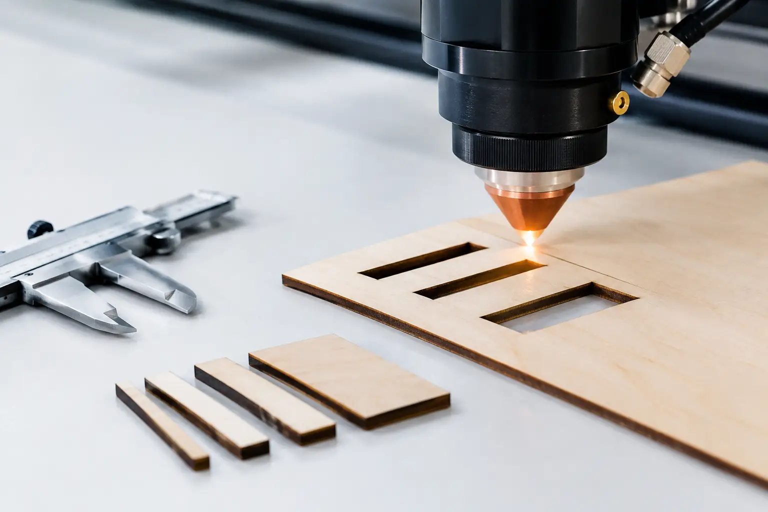
A 1 mm slot that looks perfect on a CAD drawing can be too tight for its mating tab once it is cut. That difference often comes down to kerf. This guide to laser kerf width explains how the width of a laser cut affects finished dimensions, fit-up and edge quality, so drawings can move into production with fewer surprises.
For fabricators, builders, engineers and designers, kerf is not a minor technical detail. It affects whether brackets assemble cleanly, whether decorative panels retain fine detail, and whether a batch of parts arrives ready for the next process. The right allowance depends on the material, thickness, laser settings and required tolerance.
What laser kerf width means
Laser kerf width is the amount of material removed by the laser beam during cutting. It is the width of the cut line left behind in the sheet. While a laser beam is focused to a very small point, the actual cut is wider because the beam melts or vaporises material and assist gas clears it from the cut.
A laser does not simply follow the edge of a shape. Its controller offsets the cutting path so the finished part follows the programmed dimensions. This is called kerf compensation. For an external profile, the machine cuts just outside the nominal line. For an internal hole or slot, it cuts just inside it.
When kerf compensation is correctly applied, a 100 mm square should finish close to 100 mm. When it is not allowed for, outside profiles can finish undersize and internal features can finish oversize. That is especially noticeable on press-fit tabs, bolt-hole patterns and interlocking components.
Laser kerf is often relatively narrow, commonly around 0.1 mm to 0.5 mm depending on the job. It should never be treated as one fixed figure for every material and thickness. Production settings and a test cut provide a more dependable answer than a generic number.
What changes laser kerf width?
Material type is one of the biggest variables. Mild steel, stainless steel and aluminium respond differently to laser energy and assist gas. Reflective materials, coated materials and alloys with varying composition can also require different cutting settings.
Thickness matters just as much. Thin sheet can generally be cut with a narrow, clean kerf. As material thickness increases, the cut may become wider or show a slight taper from top to bottom. The laser must maintain enough energy through the full thickness while removing molten material efficiently.
The key influences on kerf width include:
- Material type, grade and surface condition
- Sheet thickness and flatness
- Laser power, focus position and cutting speed
- Assist gas selection and pressure
- Nozzle condition, beam alignment and machine calibration
- The geometry of the feature being cut
Small internal corners, narrow slots and closely spaced features place greater demands on the process than a large external profile. Heat can build up in a tight area, particularly where the cut path changes direction frequently. A capable operator will adjust settings and cutting strategy to protect accuracy and edge quality, but there are practical limits to every material and thickness combination.
Designing parts around laser kerf
The first rule is simple: draw the part at its required finished size, not at the expected laser path. A professionally prepared laser program applies kerf compensation to achieve the nominated finished dimension. If you deliberately make holes smaller or outside profiles larger to account for kerf, then kerf compensation may be applied twice and the part can miss size.
The exception is when a job needs a deliberate clearance or interference fit. In that case, define the final functional dimension clearly. For example, if a tab needs 0.15 mm clearance on each side to assemble easily after coating, specify the finished tab and slot sizes required. This gives the cutter the information needed to choose the correct approach.
For critical parts, tolerances should be shown on the drawing rather than assumed. A general fabrication tolerance may be suitable for a guard, base plate or structural bracket. A locating feature for a machined assembly may need tighter control. The tighter the tolerance, the more valuable a first-off sample or test piece becomes.
Hole size deserves particular attention. Very small holes in thick material can be affected by taper, heat and the relationship between hole diameter and sheet thickness. A hole may be technically cut through but still be unsuitable for a precision dowel, thread-forming screw or close-tolerance fastener. In these cases, laser cutting may create the pilot feature, followed by drilling, reaming or machining where needed.
Sharp internal corners are another common issue. A laser has a finite kerf width, so an internal corner will have a small radius rather than a mathematically perfect square corner. If a square tab must seat fully into that corner, add a relief such as a dog-bone feature, or modify the mating part to provide clearance. It is a small drawing change that can prevent difficult fitting work on site.
Kerf compensation is only part of accuracy
A correct kerf offset does not guarantee every dimension on a finished component. Material movement, heat input, sheet condition and part geometry all influence the result. Long, narrow strips can shift as stress is released. Large parts may move slightly if the sheet is not flat. Intricate patterns can retain heat in localised areas and require a considered cutting sequence.
This is why process knowledge matters. A cutting provider should consider lead-in and lead-out locations, nesting direction, micro-tabs where required, and the order in which features are cut. These decisions are not always visible on the final drawing, but they affect whether parts stay stable and whether visible faces remain clean.
For decorative work, lead-in placement can be as important as dimensional accuracy. A mark in the wrong location may be hidden after fabrication, or it may be highly visible on a feature screen. For functional parts, the priority may be keeping a critical edge free from minor witness marks. Stating which faces and features matter most helps the programmer make sensible choices.
Laser versus waterjet kerf width
Laser is often the efficient choice for metal sheet where speed, fine detail and a narrow kerf are priorities. It can produce accurate profiles and small features with minimal material waste, making it well suited to brackets, panels, enclosures, signs and repetitive production components.
Waterjet cutting has a different set of advantages. Its cold-cut process uses high-pressure water, up to 60,000 PSI, with abrasive added for hard materials. Because it does not create a heat-affected zone, waterjet is often preferred where heat distortion, hardened edges or material changes are a concern. It is also highly versatile across materials that are not suitable for laser cutting, including rubber, foam, tile, stone and many composite products.
Waterjet kerf is usually wider than laser kerf, often around 0.8 mm to 1.2 mm depending on the nozzle and cutting parameters. It can also show taper if speed and quality settings are not matched to the job. However, waterjet offers excellent accuracy when programmed and operated correctly, particularly for thicker materials or heat-sensitive applications.
The best process is not always the one with the narrowest kerf. A laser may be the better option for fast, clean sheet-metal production. Waterjet may be the better option when preserving material integrity matters more than speed. For some projects, the material, edge requirement and tolerance make the decision clear. For others, comparing both processes before production can save time and rework.
How to prepare a drawing for accurate cutting
A clean DXF file is usually the most useful starting point for profile cutting. It should contain closed profiles, be drawn at 1:1 scale, and avoid duplicate lines or overlapping entities. Dimensions, material grade, thickness, quantity and required tolerance should accompany the file, particularly where fit-up is critical.
If a component mates with another part, provide both profiles where possible. Seeing the full assembly relationship makes it easier to identify whether clearance, coating thickness, bend variation or kerf-related detail needs consideration. A photo, marked-up PDF or simple note can be enough to communicate the functional intent.
Before committing to a larger run, ask for a sample if the job includes tight slots, fine perforations, press fits or highly visible architectural detail. A first-off part confirms more than kerf width. It verifies the material, finish, fit and assembly sequence under real conditions.
Measure the finished feature, not the assumption
Kerf values are useful for planning, but finished measurements are what matter. Check a representative outside profile, internal hole, slot and critical mating feature using suitable measuring equipment. For repeat jobs, retain an approved sample and record the key dimensions. This creates a practical benchmark for later batches.
For Adelaide fabricators and project teams balancing deadlines with quality, that discipline is worth the effort. Waterjet & Laser SA can assess the drawing, material and functional requirements before cutting begins, then recommend the process that gives the best balance of accuracy, edge quality and turnaround.
A well-made part starts with more than a clean outline. Specify the finished result you need, flag the dimensions that control fit, and let the cutting method be selected around the material and purpose. That is how kerf becomes a controlled production detail rather than a costly surprise.